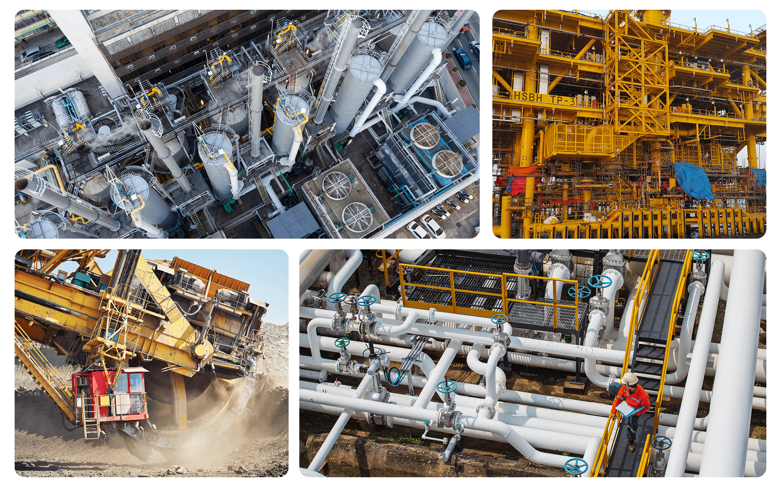
Industrial plants run on metal, and metal degrades. It is an unavoidable physical reality. In sectors like oil and gas, mining, and petrochemicals, equipment wear is a critical safety hazard and a massive financial liability. You cannot physically inspect every single square inch of piping and every pressure vessel in an operating facility every single day.
To manage asset integrity efficiently and safely, industries rely on a highly targeted, strategic approach: Condition Monitoring Locations, or CMLs.
The Anatomy of a CML
A Condition Monitoring Location is a specific, formally designated area on a piece of equipment, pipe, or pressure vessel where inspectors repeatedly measure wall thickness and material integrity to track degradation over time. Instead of treating a ten-mile pipeline as one massive inspection job, integrity engineers evaluate the system to identify the most vulnerable areas. These might be pipe elbows where fluid velocity causes heavy erosion, fluid injection points prone to chemical attack, or low points where liquids pool and induce corrosion.
These specific, high-risk spots are designated as CMLs. By routinely checking these locations, operators build a statistically sound representation of the overall health of the entire system. In a rigorous integrity program, it is a precise coordinate. It can be the exact spot where an inspector places an ultrasonic testing (UT) probe to send high-frequency sound waves through the metal, measuring the time it takes for the echo to return to determine the exact thickness of the remaining solid wall.
The Operational Gravity of CMLs
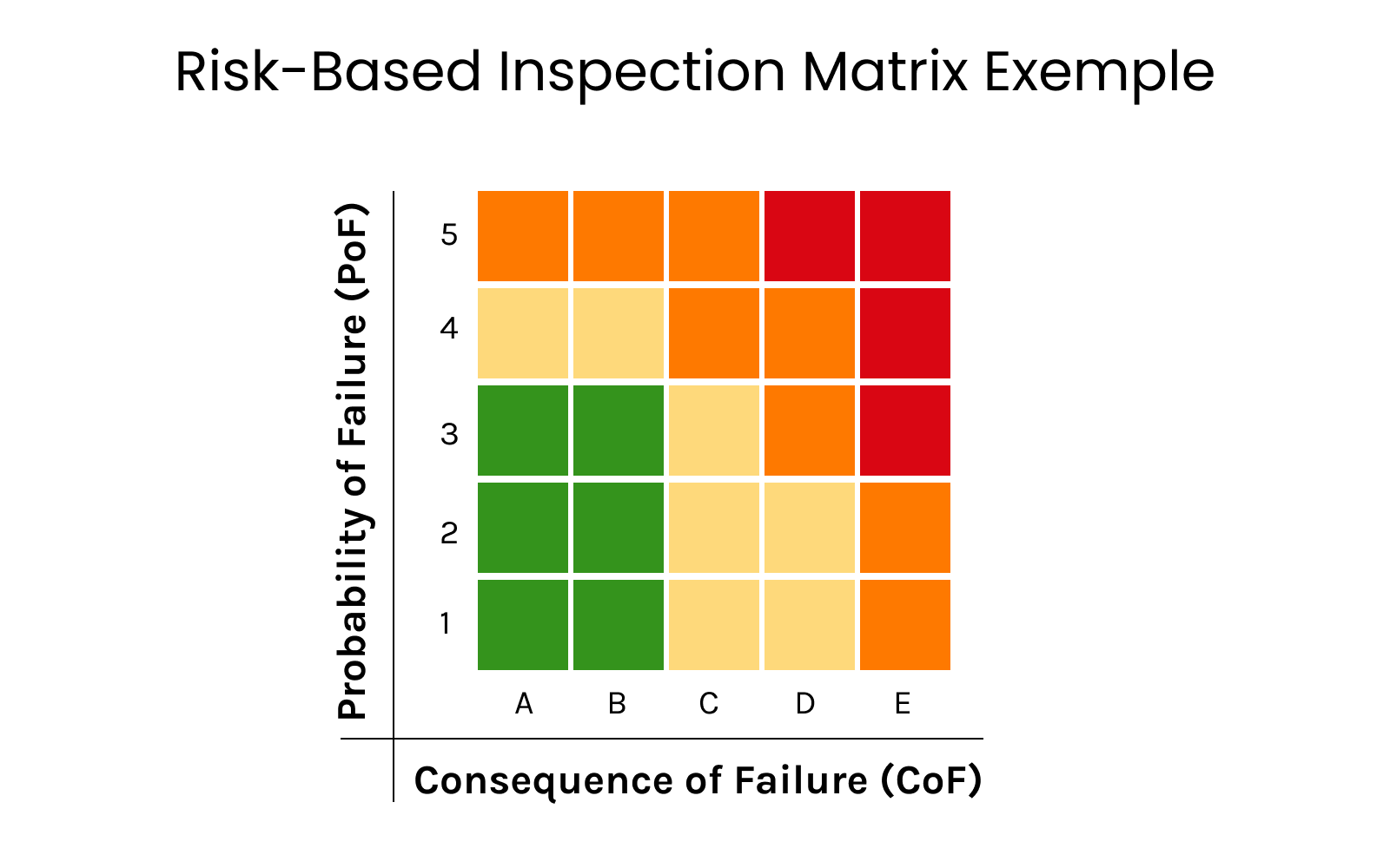
You cannot manage a risk you are not measuring. Establishing and maintaining a robust network of CMLs is the foundation of any Risk-Based Inspection (RBI) program. The primary driver here is safety and catastrophic risk mitigation. By tracking thinning walls and localized wear on a granular level, operators can catch critical material degradation long before a pipe ruptures, preventing leaks, fires, or severe environmental hazards. Furthermore, CMLs enable predictable, strategic maintenance. When you track the exact rate at which a material is degrading, you can forecast precisely when a pipe will reach its minimum safe thickness.
Regulatory compliance is also a significant driver behind structured CML management. Industry inspection standards such as API 570 for piping systems and API 510 for pressure vessels require operators to maintain documented thickness measurements, corrosion assessments, and remaining life evaluations throughout the asset lifecycle.
Within these frameworks, Thickness Measurement Locations (TMLs) and other designated monitoring points serve as the foundation for tracking degradation trends and supporting inspection interval decisions. Without a structured monitoring strategy, maintaining inspection traceability and demonstrating compliance with integrity requirements becomes substantially more difficult.
The Math Behind the Metal
To understand the management of CMLs, you have to look at the calculations that turn raw field data into engineering decisions. When an inspector takes a new thickness reading, integrity engineers use that data to calculate two critical metrics. The first relevant indicator is the Short-Term Corrosion Rate (STCR), which tells operators how fast the metal is currently degrading based on the most recent inspection interval.
The second, and perhaps most vital, calculation is the Remaining Life (RL) of the asset. This determines how many years the equipment can safely operate before it breaches the minimum required thickness for its pressure rating.
What CML Management Actually Requires
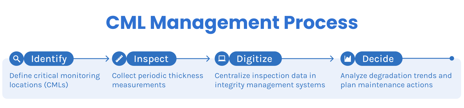
Managing these locations is a continuous, relentless cycle that demands tight coordination between field inspectors, integrity engineers, and maintenance planners. The process begins with identification. Engineers review complex piping and instrumentation diagrams alongside historical process data to determine where degradation is mathematically most likely to occur.
Once designated, inspectors are dispatched to take the baseline measurements. From that day forward, the asset is on a ticking clock. Depending on the calculated risk level, inspectors must return to that exact CML on a strict schedule, sometimes every few months, sometimes every few years. Historically, the data gathered from these inspections lived on clipboards or isolated spreadsheets. Today, modern integrity programs are transitioning to structured, digital databases. When a CML is digitized, the asset profile becomes a complex data payload that feeds directly into maintenance software.
This digital structure is exactly what allows engineering teams to pull away from filing cabinets and start managing their assets dynamically.
The Field Bottlenecks Shattering Traditional Workflows
In theory, the CML management cycle is deeply logical. In the physical reality of a plant, it is incredibly messy. Mid-sized to large facilities often juggle tens of thousands of active CMLs, and attempting to manage them through traditional means creates severe, costly bottlenecks. The most notorious issue is the exact spot problem. For a degradation rate calculation to be accurate, an inspector in 2026 needs to measure the exact same two-inch circle that a previous inspector measured in 2024. If they place the probe just a few inches away, the thickness might be drastically different, completely skewing the data.
Physical tags fall off, paint fades, and scaffolding obscures access. Finding the precise location manually is an exercise in frustration that routinely corrupts data integrity.
Then comes the issue of information silos. Field workers taking measurements in the field often write numbers on paper, and this data won’t be synced until the end of a shift or the end of a week. This creates a massive time lag between when a measurement is taken in the field and when an engineer actually runs the Remaining Life calculation in the office.
Finally, physical access is a massive financial drain. Many CMLs are located fifty feet in the air or in complex, confined spaces. Sending a team to build scaffolding just to take a single ultrasonic reading takes days, costs thousands of dollars in labor, and introduces unnecessary safety risks for a task that takes ten seconds to perform once reached.
Connecting the Field to the Future: The Digital Reality
The challenges of CML management are ultimately spatial and data-driven. Standard spreadsheets and 2D blueprints simply cannot keep up with the physical complexity of a modern industrial facility alongside its modifications. Asset management is rapidly moving toward specialized, visual technologies to resolve these exact bottlenecks.
Spatial computing is solving this exact spot problem entirely. By utilizing industrial mixed-reality techniques or advanced spatial reconstruction, the 3D coordinates of a CML are permanently locked in digital space. An inspector walking through the plant sees a digital overlay guiding them to the exact millimeter where the reading must be taken.
This significantly reduces locator ambiguity and improves inspection repeatability over time. However, location accuracy alone does not fully resolve the broader challenge surrounding CML management.
In many traditional integrity workflows, inspection data is still fragmented across spreadsheets, disconnected databases, static reports, and 2D engineering drawings. While these systems store measurements effectively, they often provide limited operational context around where degradation is occurring inside the physical facility.
This is one of the main reasons Digital Twin environments are becoming increasingly relevant in asset integrity programs. A Digital Twin serves as a continuously contextualized digital representation of the physical plant, integrating spatial geometry, asset hierarchy, inspection history, and operational data into a unified environment.
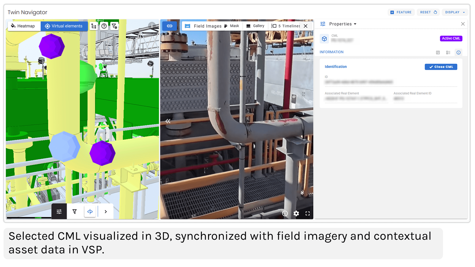
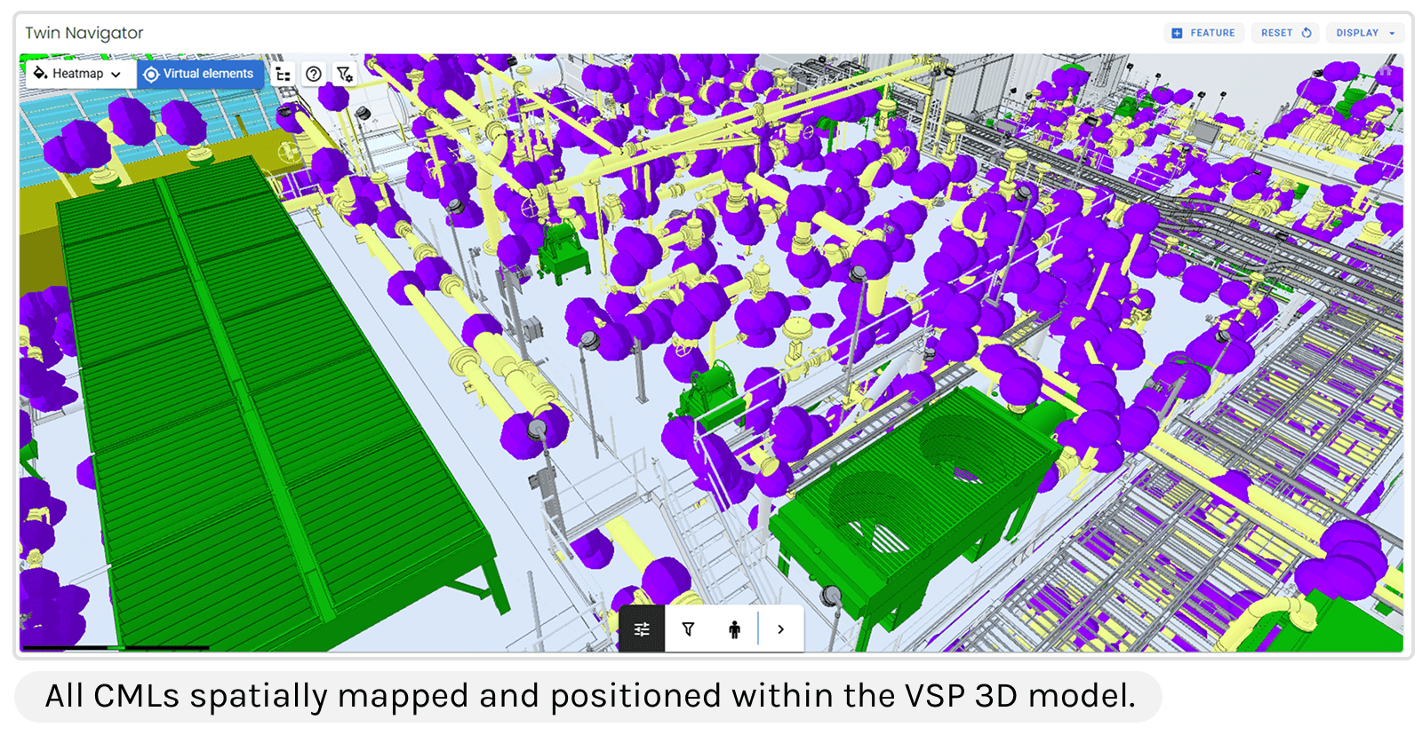
Instead of reviewing isolated rows of thickness measurements, engineers can visualize CMLs directly within the 3D context of the asset itself. Inspection locations, degradation histories, and anomalous readings become spatially traceable, helping teams interpret integrity conditions with greater consistency and operational visibility.
Beyond that, Artificial Intelligence is tying this ecosystem together. When an integrity team is managing 50,000 CMLs, human engineers cannot manually analyze every single trendline fast enough to be proactive. AI engines process historical thickness data the second it is uploaded from the field. The system runs the math in the background, automatically flagging specific CMLs that are degrading faster than their historical baselines predict.
Managing CMLs will always be the cornerstone of heavy industrial safety. But the methodology is evolving.
Conclusion
The reality of heavy industry is that degradation will still go on, and the operational demand to run safely while reducing maintenance costs is only going to increase. For decades, integrity teams have fought a frustrating battle against corrupted data, faded physical inspection tags, and bloated scaffolding budgets just to get a basic read on their equipment health.
Transitioning Condition Monitoring Locations from isolated spreadsheets and flat 2D drawings into a dynamic, spatial environment is a baseline requirement for competitive operations. When you know the exact physical coordinates of your degradation and have the 3D context to visualize it instantly, the entire operational dynamic shifts.